The Foucault Pendulum at the United Nations
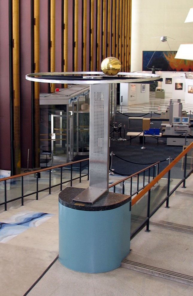
The pendulum pedestal was designed by architect G. Rietveld.
On 7 December 1955, Mr. H. Luns, Dutch Foreign Minister, presented a Foucault Pendulum to the Chairman of the United Nations General Assembly on behalf of the people of the Netherlands.
A Foucault Pendulum is a simple device to demonstrate the rotation of the Earth. The principle of the Foucault Pendulum was first demonstrated in Paris in 1851 by the noted French physicist Jean Bernard Léon Foucault.
While scientists argued that the Earth is rotating, the introduction of the Foucault Pendulum in 1851 was the first simple proof of the Earth's rotation in an easy-to-see experiment. When hung from a fixed point, the plane in which the pendulum swings appears to rotate due to the rotation of the earth beneath it. At the latitude of New York, the pendulum takes approximately 36 hours and 45 minutes to complete its rotation cycle.
A century after Foucault's demonstration of the Earth's rotation, the Foucault Pendulum at the UN was designed and built in the research laboratory of Koninklijke Philips N.V.
The UN pendulum is a 200 pound (91 kg) gold-plated sphere 12 inches (30 cm) in diameter partially filled with copper and suspended from a fixed point in the ceiling, 75 feet (23 meters) above the ceremonial staircase, by a stainless steel wire. A universal joint allows it to swing freely in any direction. The sphere passes directly over a raised metal ring at the centre that contains an electromagnet which induces a current in the copper inside the ball. This supplies the necessary energy to overcome friction and air resistance and keeps it swinging uniformly.
The shaft supporting the electromagnetic ring bears the following message from Queen Juliana: “It is a privilege to live this day and tomorrow. Juliana”
Driving the UN Foucault Pendulum
Left to itself, air resistance will slow down any pendulum until it stops swinging. A grandfather clock uses a wound-up spring to add a little energy at every swing to sustain the pendulum motion.
Very large Foucault pendulums in museums of science around the world use electrical energy. Most use a mechanism that pushes the suspension wire near the top suspension point. See Academy Pendulums, who built their first Foucault Pendulum for the California Academy of Sciences in 1951 and their third for the Boston Museum of Science in 1957.
The UN pendulum is unusual in that it uses an electromagnet beneath the pendulum bob to push on a copper plate embedded in the bob.
The Philips' lab design was based on R. Stuart Mackay's article "Sustained Foucault Pendulums" in the American Journal of Physics, 1953, vol.21, p,180.
J. A. Haringx and H. van Suchtelen of Koninklijke Philips N.V. described the engineering design in their article "The Foucault Pendulum in the United Nations Building in New York" in the Philips Technical Review, 1957/58, No.7-8, vol.19, p.236
The following (in italics) is adapted from their article.
The moment at which the coil is energized is
determined by the moment at which the suspension wire
touches a circular ring near the top suspension point. A delay circuit,
which also controls the duration of energization,
ensures that the current in the coil is switched on at
a specific time after the centre of the bob passes the
axis of the coil.
|
|
|
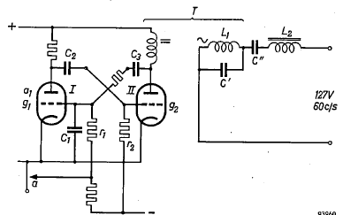
Philips original of the Transductor T (Saturable Reactor)
|
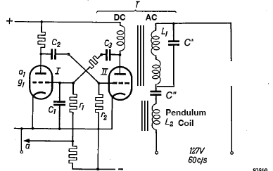
DC and AC winding share magnetic core of Saturable Reactor T
|
The anode load of tube II in the
circuit includes the DC winding of a
transductor T. The AC winding II of this transductor
is connected in series with the drive coil L2
and a capacitor C". In addition, another capacitor
C' is connected in parallel with L1, When the DC
coil of the transductor is not energized, the circuit
L1-C' is in [parallel] resonance and represents such a high
impedance that the current through L2 is only 85mA.
(The 127V AC 60cps voltage is
applied to the coil when the DC current of anode II desaturates the transductor magnetic core, allowing AC to flow through L1 and L2.)
When the transductor is energized by the anode
current of tube II, the self-inductance of L1 is
reduced by about a half. The capacitance of C" is
such that the whole circuit now comes into series
resonance, whereupon the current through L2 rises
to 240 mA. The ratio between operating and
quiescent currents does not seem particularly large,
but it must be remembered that the energy transferred
is proportional to the square of the current.
In this way about 0.035 joule is supplied to the
bob in each period, which is sufficient to provide an
amplitude of swing of the required value.
The power
applied to the coil is 127V x 240mA = 30.5 watts (or joules/second).
If the energizing duration is 1 second, the energy input to the coil is 30.5 joules, but only 1/100th
of this (0.035 joule) is applied to the bob by magnetic induction, which falls off rapidly (as the inverse square of the distance of the receding bob).
Replacing the Pendulum Electronics with a Solid State Device

Stuart Cody at the Foucault Pendulum
In 2023, the pendulum electronic control system failed and Stuart Cody of Automated Media Systems got it working again by increasing voltage from 110V to the nominal 127V in the original specifications.
But the electronics then had another failure in 2025. Cody suspected that the failure was caused by corrosion of the circular ring around the top of the suspension wire, making the electrical content intermittent.
The seventy-year old electronic control box, located four floors above the energizing coil and forty feet below the top of the suspension wire, is another potential source of errors.
Cody proposed mounting an led-photosensor proximity detector immediately below the pendulum bob, inside the coil. A reflection off the bottom of the passing bob would be the new initial signal to the delay circuit. A fraction of a second after the bob leaves the center of its swing, the coil would be energized to give the bob a kick. The complete control system might be located in the pedestal base, making it much easier to maintain.
Cody turned to an old SMPTE colleague and collaborator on synchronizing video cameras, Bob Doyle, who had patented an led-photosensor electronic circuit to synchronize a Super8 movie camera with a sprocketed magnetic film recorder in the 1970's. Doyle and his son Rob joined Cody to develop a solid state control box that could be located in the pendulum pedestal.
Bob Doyle used Anthropic Claude AI to design a solid state equivalent to the original pendulum electronics. Here is that exchange...
Claude, Can you draw the UN Foucault Pendulum control as a standard electronic circuit diagram with a Fairchild QRD1112 as optical sensor stage?
I'd be happy to design a Foucault Pendulum impulse control circuit with a Fairchild QRD1112 optical sensor. To make sure I get it right, a few quick questions: What do I know about your setup:
* QRD1112 = reflective IR sensor (emitter + phototransistor in one package)
* Typical Foucault pendulum control = detect bob passing center, fire an electromagnet coil (kick coil} to sustain swing.
*1 — Sensor stage (QRD1112),
*2 — Signal conditioning (LM393 comparator),
*3a — One-shot pulse timer delay (NE555),
*3 b— One-shot pulse timer energizing period (NE555),
*4 — Kick-coil driver (Crydom D2410)
Here's the full schematic. Walking through each stage:
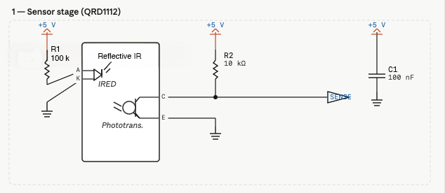
Stage 1 — QRD1112 sensor. The on-chip IR LED runs through R1 (100 Ω) from the 5 V rail, setting its current to ~30 mA. The phototransistor has its collector pulled up via R2 (10 kΩ), so the SENSE net sits near +5 V in ambient light and pulls low when the bob reflects IR back at the sensor.
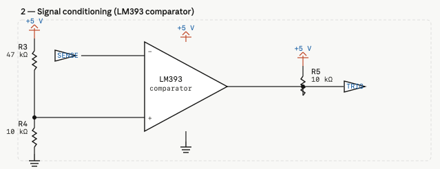
 Stage 2 — LM393 comparator. The SENSE signal goes to the inverting input (−). A resistor divider R3/R4 (47 kΩ/10 kΩ) sets the threshold at ~0.9 V on the non-inverting input (+), so the open-collector output goes high (via pull-up R5) only when the phototransistor sees a strong reflection — i.e., the bob is directly over the sensor. The output becomes the TRIG net.
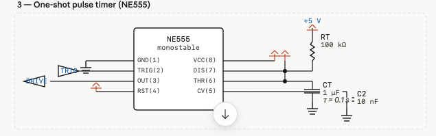
 Stage 3 — NE555 monostable. A falling edge on TRIG fires a single clean output pulse. RT (100 kΩ) and CT (1 µF) set the pulse width to roughly τ = 1.1 × RT × CT ≈ 110 ms — enough time for the coil to deliver a good kick without holding it on so long the bob swings back into the field. C2 (10 nF) on the control voltage pin suppresses noise. RST is tied high.
 Stage 4, with Crydom D2410 solid state relay to drive coil, with an RC snubber circuit, in series across L1 and L2 output of the SSR)
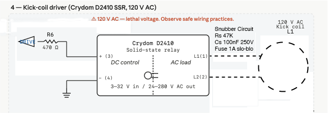 The D2410 is a DC-control/AC-load SSR: control input 3–32 V DC, load 24–280 V AC up to 10 A — well suited here. The 555's 5 V output drives the control side directly (no gate resistor or pull-down needed, just a current-limit resistor) On the AC load side, a snubber (RC) across the SSR output is good practice to suppress transients from the inductive coil. A fuse on the AC hot line is mandatory.
D2410 control side. The 555's DRIVE output goes through R6 (470 Ω) to the SSR's + terminal (pin 3). The D2410's internal LED draws about 7–15 mA, and 470 Ω from 5 V puts you comfortably in that range. The control − (pin 4) goes to DC ground. No pull-down resistor is needed — the SSR's input has a defined off-state threshold and there's no floating gate to worry about.D2410 load side. The AC hot line passes through fuse F1 (1 A slow-blow) before reaching SSR pin 1 (L1). The coil connects between SSR pin 2 (L2) and the AC neutral.
The D2410 uses a triac output that turns off at the next zero-crossing, which is actually helpful here — it naturally rounds off the coil's current edges. Snubber network Rs/Cs (47 Ω + 100 nF/250 V) is placed directly across the SSR load pins. An inductive coil without a snubber will generate voltage spikes at turn-off that stress the SSR's internal triac. The 250 V AC rating on Cs is mandatory — a standard 50 V cap here will fail catastrophically.
Safety notes worth emphasising:* Fuse F1 must be on the hot (L) line, not neutral* Keep all 120 V AC wiring physically separated from the 5 V DC side — ideally in a separate enclosure compartment* The D2410 chassis gets warm under load; it's designed to be bolted to a heatsink panel* The DC ground and AC neutral must not be connected together unless your 5 V supply is specifically rated for that configuration (most USB supplies are isolated — keep it that way)
Claude, Does the Crydom D2410 output need an RC snubber circuit for an inductive coil output?
Yes, if your Crydom D2410 is driving an AC inductive load (like a relay coil, solenoid, or motor), an RC snubber circuit and/or a Metal Oxide Varistor (MOV) is highly recommended. [1, 2, 3]
While the D2410 utilizes robust back-to-back SCR outputs and has an internal snubber network for basic protection, highly inductive loads can generate severe voltage spikes and high commutation upon turn-off. Without external suppression, these inductive kickbacks can damage or destroy the internal thyristors or cause the relay to fail to turn off properly. [1, 2, 3, 4, 5]
To protect the relay output, consider the following methods:
* External RC Snubber: Place a series RC network across the SSR output terminals or directly across the inductive load. A common and effective value for 230V AC applications is a .1 μF (100nF) X-rated capacitor in series with a 47 to 100-ohm resistor. Alternatively, or in addition to the RC network, you can wire an MOV in parallel with the load. Choose an MOV with a voltage rating slightly higher than your nominal line voltage (e.g., a 275V AC MOV for a 230V line). [1, 2]
Two timers are needed, not just one, first 3a, a very short delay after the bob passes the photosensor, then 3b, variable energization time (maybe .2 to .5 seconds?)
The D2410 is a DC-control/AC-load SSR: control input 3–32 V DC, load 24–280 V AC up to 10 A — well suited here. The 555's 5 V output drives the control side directly (no gate resistor or pull-down needed, just a current-limit resistor) On the AC load side, a snubber (RC) across the SSR output is good practice to suppress transients from the inductive coil. A fuse on the AC hot line is mandatory.
D2410 control side. The 555's DRIVE output goes through R6 (470 Ω) to the SSR's + terminal (pin 3). The D2410's internal LED draws about 7–15 mA, and 470 Ω from 5 V puts you comfortably in that range. The control − (pin 4) goes to DC ground. No pull-down resistor is needed — the SSR's input has a defined off-state threshold and there's no floating gate to worry about.D2410 load side. The AC hot line passes through fuse F1 (1 A slow-blow) before reaching SSR pin 1 (L1). The coil connects between SSR pin 2 (L2) and the AC neutral.
The D2410 uses a triac output that turns off at the next zero-crossing, which is actually helpful here — it naturally rounds off the coil's current edges. Snubber network Rs/Cs (47 Ω + 100 nF/250 V) is placed directly across the SSR load pins. An inductive coil without a snubber will generate voltage spikes at turn-off that stress the SSR's internal triac. The 250 V AC rating on Cs is mandatory — a standard 50 V cap here will fail catastrophically.
Safety notes worth emphasising:* Fuse F1 must be on the hot (L) line, not neutral* Keep all 120 V AC wiring physically separated from the 5 V DC side — ideally in a separate enclosure compartment* The D2410 chassis gets warm under load; it's designed to be bolted to a heatsink panel* The DC ground and AC neutral must not be connected together unless your 5 V supply is specifically rated for that configuration (most USB supplies are isolated — keep it that way)
Claude, Does the Crydom D2410 output need an RC snubber circuit for an inductive coil output?
Yes, if your Crydom D2410 is driving an AC inductive load (like a relay coil, solenoid, or motor), an RC snubber circuit and/or a Metal Oxide Varistor (MOV) is highly recommended. [1, 2, 3]
While the D2410 utilizes robust back-to-back SCR outputs and has an internal snubber network for basic protection, highly inductive loads can generate severe voltage spikes and high commutation upon turn-off. Without external suppression, these inductive kickbacks can damage or destroy the internal thyristors or cause the relay to fail to turn off properly. [1, 2, 3, 4, 5]
To protect the relay output, consider the following methods:
* External RC Snubber: Place a series RC network across the SSR output terminals or directly across the inductive load. A common and effective value for 230V AC applications is a .1 μF (100nF) X-rated capacitor in series with a 47 to 100-ohm resistor. Alternatively, or in addition to the RC network, you can wire an MOV in parallel with the load. Choose an MOV with a voltage rating slightly higher than your nominal line voltage (e.g., a 275V AC MOV for a 230V line). [1, 2]
Two timers are needed, not just one, first 3a, a very short delay after the bob passes the photosensor, then 3b, variable energization time (maybe .2 to .5 seconds?)
Building the Prototype Circuit
The plan is to realize the above electronic design on a small circuit board about the same size as the Crydom D2410 SSR and fit them and a stubber with an MOV Varistor into a small metal enclosure. This circuit replaces the old vacuum tubes of the 1950's control box. It does not replace the saturable reactor or transductor, which is still being researched. The output of the Crydom SSR can be rectified to provide the DC input to the control winding of a saturable reactor.
The saturable reactor's AC winding, L1, in parallel resonance with C', has such a high impedance that the current through the coil L2 is only 85mA.
When the DC current through the control winding is increased it saturates the transductor magnetic core, increasing the AC flow through C" and the coil L2, which are in series resonance just above the 60Hz AC, reducing impedance to the DC resistance 288 ohms. The current through the coil rises to 240 mA, enough to give the pendulum bob a gentle "kick" to restore the energy lost to air resistance.
The saturable reactor amplification of voltage may be replaced by a voltage transformer increasing AC voltage from 120V to 480V, input directly to the series-resonant capacitor C" and inductor coil L2, which will amply voltage at the coil to thousands of volts.
The original capacitor C" in 1950's control box was actually three 2μF capacitors in series (equivalent to .667μF), reducing the voltage across each capacitor to several hundreds of volts.
The series resonant frequency (1/2π√LC), with the L2 coil equal to 10 Henry, was 62 cps, just above the AC line frequency 60Hz.
To reduce the voltage per modern metallized polypropylene capacitor below their 500VAC rating, we built a capacitor bank of six 5μF and two 7.5μF capacitors in series (equivalent to .682μF), lowering the AC voltage per capacitor more than two times to about 400V and the resonant frequency to 61 cps, slightly closer to the 127V 60Hz source, which improves Q.
A heavy (21 lbs) 10 Henry choke is used to measure the voltages and currents in the series resonant circuit before applying the new solid-state electronics to the original L2 coil driven by the Philips control box.

Breadboard versions of the circuit. When the led light is reflected back into the photosensor by a finger passing over, the first 555 timer chip delays a fraction of a second and then the second 555 turns on for the energization time.
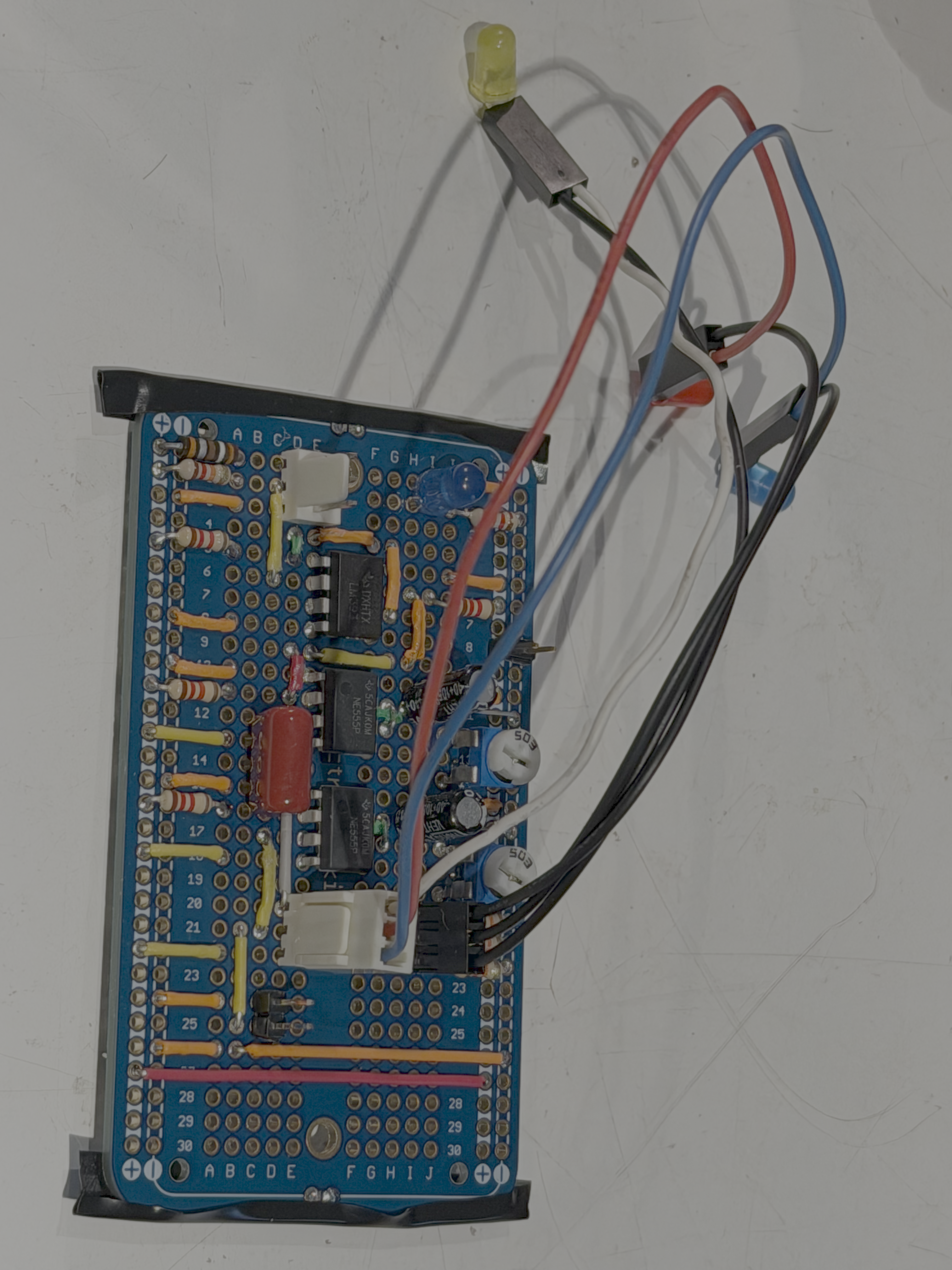
Soldered version of the circuit, with yellow, red, and blue leds to be mounted in the case, to signal detection of the bob, delay, then energization time.
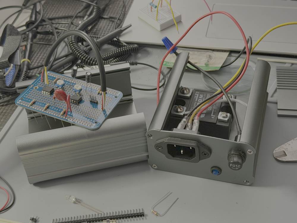
The electronic circuit board and the Crydom SSR are about the same size.
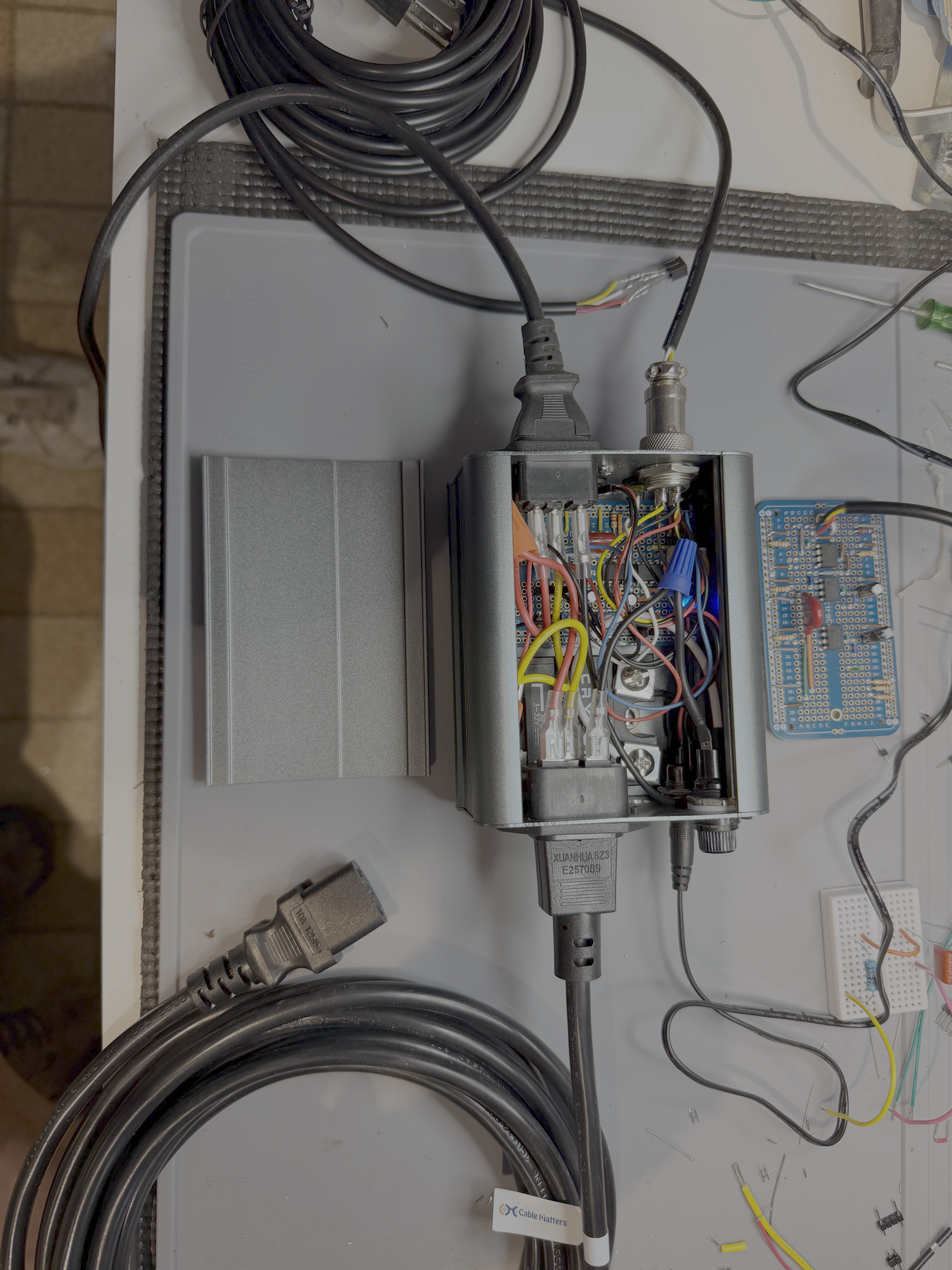
The circuit board and Crydom inside the case with heavy duty AC input and output power cords.